
Bridging 1.8 V and 3.3 V: level translators from three Chinese suppliers
A controller, sensor and communications module can agree on a protocol while using different electrical interfaces. One device may run its I/O at 1.8 V, another at 3.3 V, with some connections still using 5 V. Level translators allow those signals to cross voltage domains when the devices cannot connect directly.
For engineering and sourcing teams considering Chinese suppliers, 3PEAK, SGMICRO and EnergyMath provide specific two-channel and eight-channel options. Their documentation shows why interface type, loading and direction control should shape the shortlist before headline data rates do.
1. Match input thresholds and voltage tolerance
A logic high is a voltage range accepted by the receiver. Whether a 1.8 V output can drive a 3.3 V input depends on that input's threshold. In the reverse direction, the receiving 1.8 V port must tolerate the applied voltage. Check thresholds and voltage tolerance before deciding whether translation is needed. Some devices support direct connection across the relevant voltage domains.
A dual-supply translator follows the supply on each side: side A uses one rail, side B another, and the output is expressed at a level the receiving device can recognize. The January 2026 datasheet for 3PEAK's TPT20208 shows a typical connection between a 1.8 V controller and a 3.3 V system. Its A-side supply range is 1.2 V to 3.6 V and its B-side range is 1.65 V to 5.5 V, with the A-side voltage required to be no higher than the B-side voltage during normal operation. The supplier lists it as an industrial-grade production device.
The translated quantity is a logic signal. LDOs and DC/DC converters supply power; level translators convey interface data at suitable voltage levels.
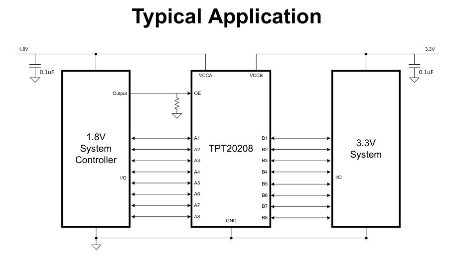
Figure 1. The TPT20208 manufacturer's typical application connects 1.8 V and 3.3 V systems. Source: the January 2026 datasheet revision. This is a reference circuit.
2. Open-drain and push-pull interfaces need different comparisons
UART and GPIO signals commonly use push-pull outputs that actively drive both high and low levels. Conventional I²C uses open-drain signaling: a device pulls the line low, then releases it so a pull-up resistor can establish the high level. This supports a shared bus, with the rise time influenced by resistance and bus capacitance.
SGMICRO's SGM4553YVS supports both interface types. Its November 2025 datasheet gives rates of 24 Mbps for push-pull operation and 2 Mbps for open-drain operation. The part is a two-channel automatic bidirectional translator in a VSSOP-8 package, listed by the supplier as in production. Its applications include I²C/SMBus, UART and GPIO. A two-channel device can avoid unused channels when only two signals cross a voltage boundary.
Compare data rates together with output type, supply voltage and load. The TPT20208's 100 Mbps specification, for example, applies to push-pull operation with 3.3 V and 5 V supplies and 15 pF loads on both sides. A 1.8 V to 3.3 V design needs the timing data for its own operating conditions.
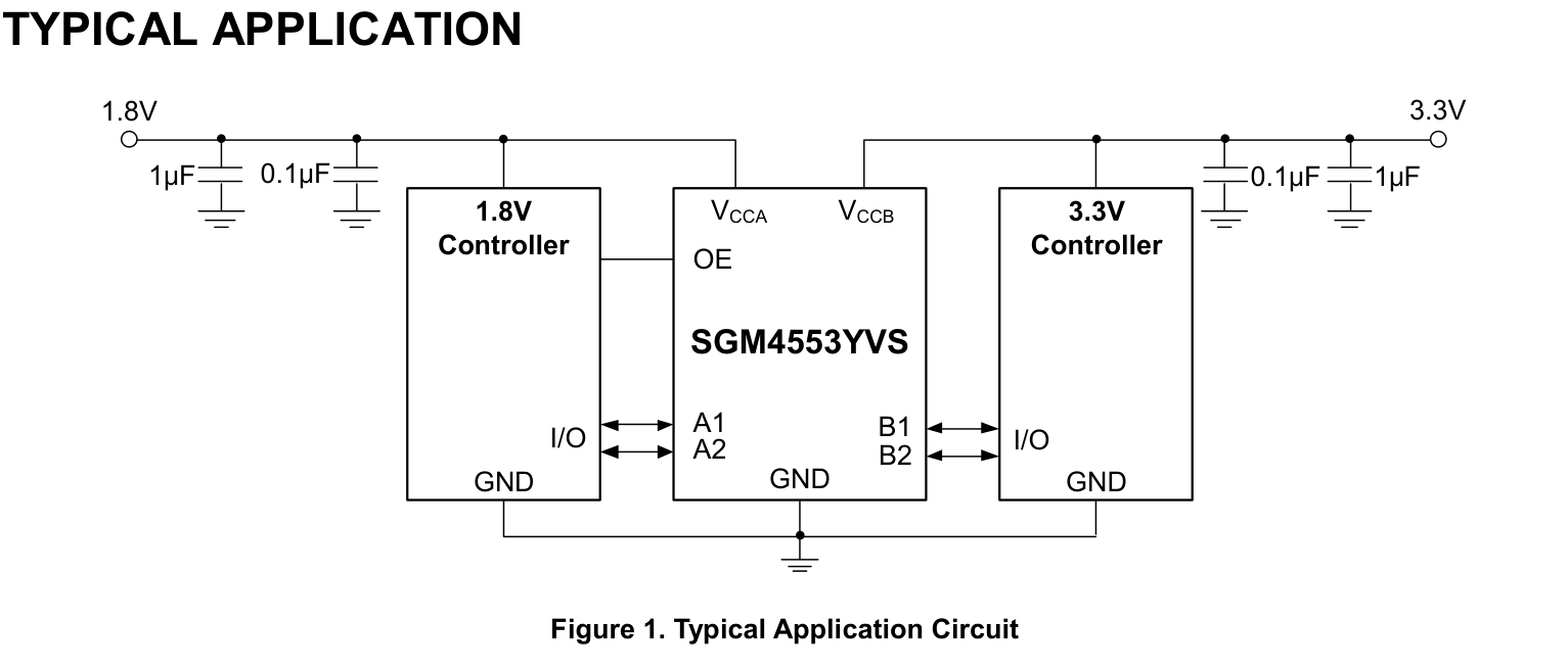
Figure 2. SGMICRO's two-channel SGM4553YVS reference circuit, reproduced from its November 2025 Rev. A datasheet.
3. Channel count and direction control divide the product options
The TPT20208 provides eight channels for push-pull translation. EnergyMath's EXS0108 is also an eight-channel automatic bidirectional device, but its October 2025 datasheet specifies operating conditions for both push-pull and open-drain applications. EnergyMath's March 2026 product-handbook introduction also identifies EXS, LVC, AVC and AXC translation families.
These two eight-channel devices therefore have different interface emphases. Check whether the signals can share the translator's supply rails, and map any direction requirements before combining lines in one package.
| Supplier | Device | Interface emphasis | Documentation reviewed |
|---|---|---|---|
| 3PEAK | TPT20208 | Eight-channel automatic bidirectional translation; push-pull applications | January 2026 datasheet; listed in production |
| SGMICRO | SGM4553YVS | Two-channel automatic bidirectional translation; open-drain and push-pull | November 2025 datasheet; listed in production |
| EnergyMath | EXS0108 | Eight-channel automatic bidirectional translation; separate open-drain and push-pull conditions | October 2025 datasheet; March 2026 family introduction |
Direction-controlled parts offer another arrangement. 3PEAK's T74L2T45 uses a DIR pin to select A-to-B or B-to-A transmission. Its August 2026 datasheet describes this behavior, while the supplier's selector still marked it as Preview on September 28. Procurement should confirm its supply schedule separately.
Automatic bidirectional devices avoid a direction-control wire; DIR-controlled devices let the system set the direction explicitly. Driving the same line from both ends at once can still cause contention.
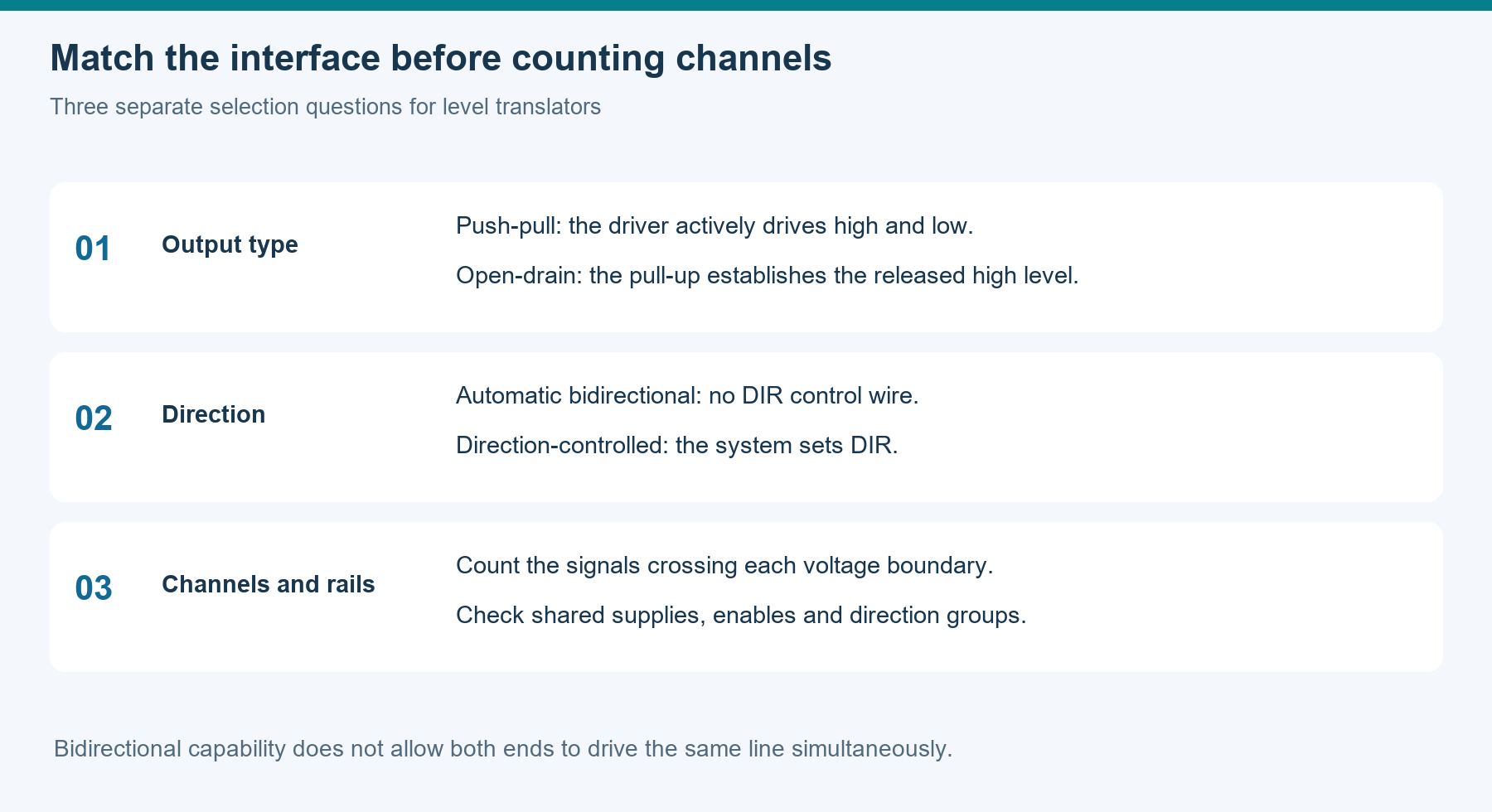
Figure 3. Assess output type, direction control and channel organization separately, then match their combination to a device.
4. Qualify the translator on the target board
A circuit that communicates normally on a bench can behave differently with longer traces, more connectors or heavier loads. The SGM4553YVS and EXS0108 datasheets discuss loading and routing because edge-acceleration circuitry in automatic bidirectional devices interacts with line capacitance, reflections and driver characteristics.
Measure high and low levels, edge shape and propagation delay at the actual receiver. That waveform captures the combined behavior of the translator, traces and external circuitry.
Sleep and wake-up create another test case. If the controller is powered while a peripheral remains off, a signal may feed current into the unpowered port. The TPT20208, SGM4553YVS and EXS0108 each provide power-down-related functions, with device-specific conditions. Include OE state, pull-up supply connections and slow supply ramps in board testing.
Procurement should request complete ordering codes and document package, temperature range and interface mode. Engineering should keep the corresponding board-test records. A shared channel count or bidirectional description establishes only part of the functional match. Changes to pull-ups, control wiring or board layout also contribute to qualification cost.
For an existing design, compare the original and candidate parts with waveforms captured under the same conditions. A second source is useful when it fits the target circuit and its sample and production-supply arrangements support the project.
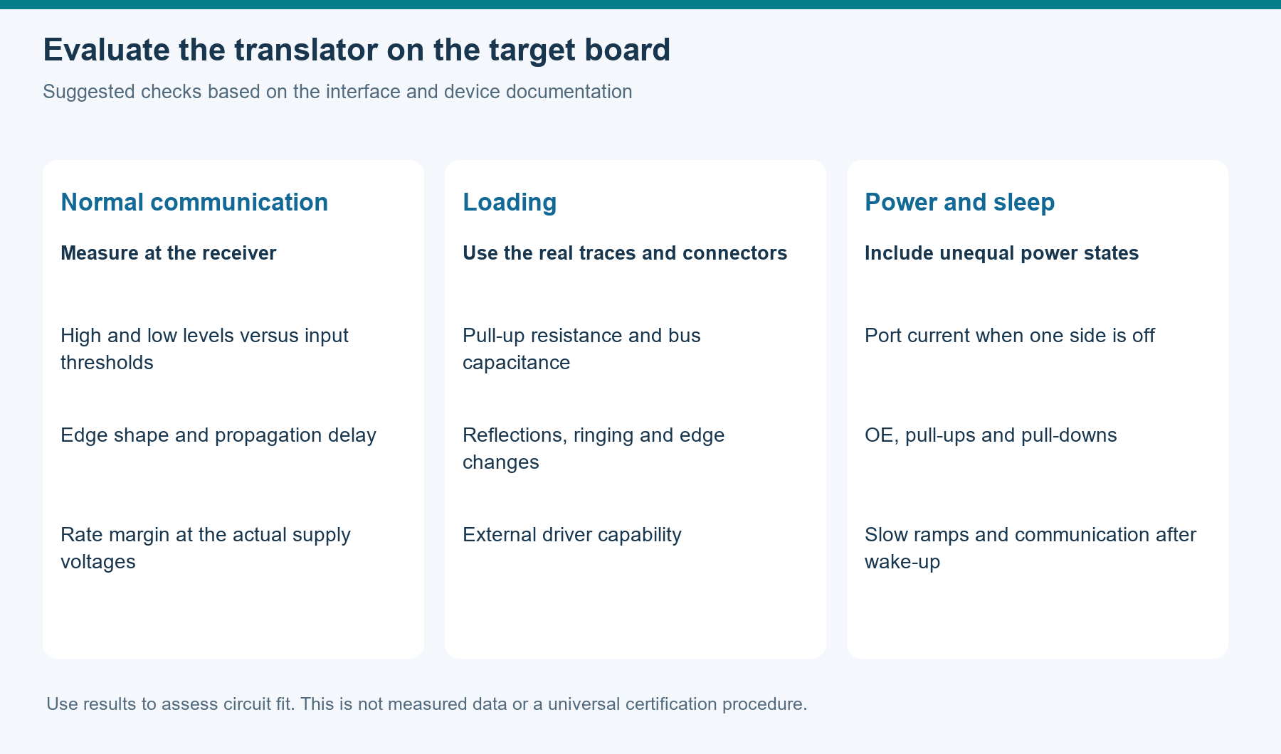
Figure 4. Suggested checks for normal communication, load changes, power-up and sleep. Choose test conditions for the actual interface.
The supplier options now span two and eight channels, open-drain and push-pull interfaces, and automatic or explicit direction control. Mapping each signal to those requirements gives engineering teams a practical way to select devices for testing between 1.8 V and 3.3 V domains.
This article uses manufacturer information reviewed through September 28, 2026. Final specifications and supply status should follow the latest manufacturer documentation and project validation.