
One component in a LiDAR transmitter is easy to underestimate: the high-voltage capacitor.
On a datasheet, it may offer only a few hundred picofarads to 1 nF. In a nanosecond pulse circuit, however, it must deliver current to the laser diode in an extremely short time. Capacitance and voltage are only the starting point. Placement, electrode structure, pads and bond-path length all affect the resulting pulse waveform.
That is the main trap when comparing Fenghua, FOIN Micro, Murata, MACOM and Launchip: products called “high-voltage capacitors” may address quite different engineering problems.
1. In nanosecond circuits, loop parasitics can be the limiting factor
TI's TIDA-01573 LiDAR reference design presents a 60 A, 1 ns pulse operating point. It emphasizes that power-loop capacitors must store sufficient charge while minimizing parasitic inductance along the current path.
The design places capacitors on both sides of the laser diode to form two parallel power loops, with a separate Kelvin return path for the gate drive. High-speed pulse design therefore involves much more than selecting a low-ESL capacitor: the capacitor, laser, switch and return path must be considered together.
For an order-of-magnitude estimate, assume 0.5 nH of loop inductance and a current slew rate of 10 A/ns. From V = L × di/dt, the induced voltage is 5 V. This is an illustrative calculation, not a measured device result, but it shows why even short connections that seem negligible in conventional circuits matter at nanosecond timescales.
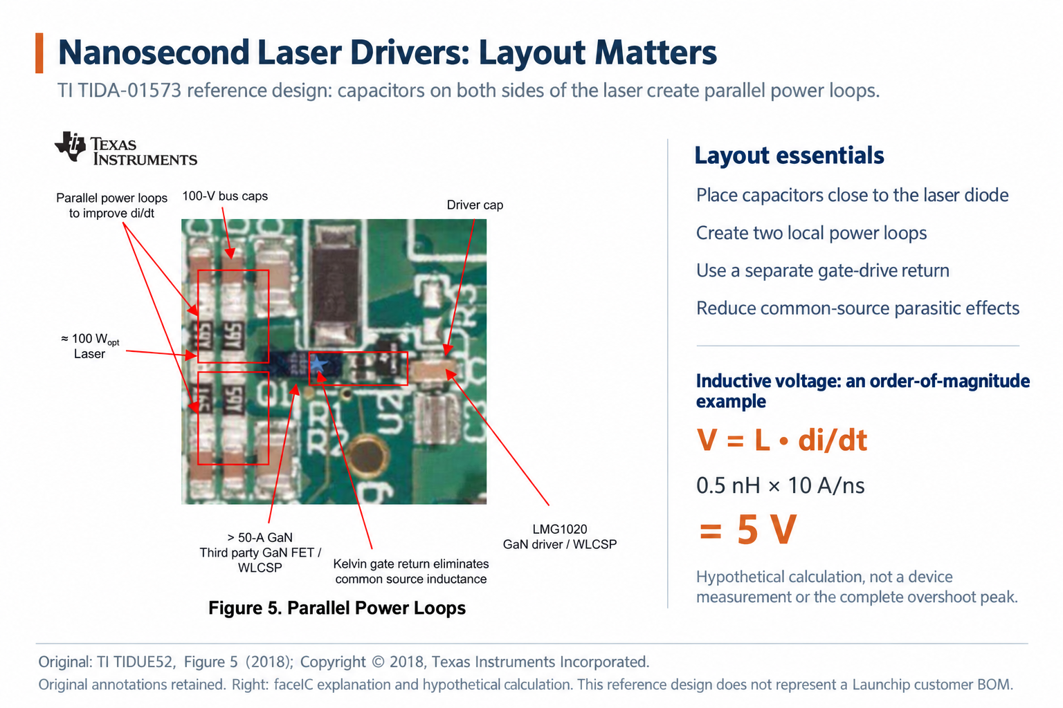
The first selection questions should therefore extend beyond “how many nF and volts?” Where will the capacitor sit, and what path will the current follow to the laser?
2. Five products represent three selection routes
The first route is the established board-level MLCC approach. Fenghua's 0603CG102J101NT, for example, is a 1 nF, 100 V, C0G capacitor in a 0603 surface-mount package. Its strengths are a standard footprint and mature assembly and supply infrastructure. Where board space and loop parasitics meet the requirements, an MLCC remains a practical choice.
The second route uses compact silicon capacitors with top and bottom electrodes for vertical connections. FOIN Micro's HBC12411N10333-KTW provides 330 pF, a 400 V breakdown voltage, a 0101 footprint and 100 μm thickness. Murata's 935146521410-F1T provides 1 nF in a 0202 format, with a 150 V breakdown voltage and dimensions of 0.50 × 0.50 × 0.10 mm. Launchip's LHV102WB6K1501 also provides 1 nF on a 0.50 × 0.50 mm die in the 100 μm thickness class. These parts aim to shorten local power loops, but their capacitance and voltage positioning differ.
The third route is bare silicon die for high continuous operating voltage. MACOM's MKVC-5A100 also provides 1 nF, but with a 500 V working voltage on a die measuring 100 mil square. Its larger die area supports greater working-voltage headroom, addressing different constraints from low-profile 0202 products.
These products cannot simply be ranked by the voltage number. Fenghua and MACOM specify rated or working voltage; FOIN Micro's 400 V and Murata's 150 V are breakdown voltages. Launchip's public catalog uses a withstand-voltage label, while its detailed datasheet distinguishes rated working voltage from breakdown voltage. Two 1 nF parts are not necessarily interchangeable, and two 150 V labels may describe different limits.
3. Launchip LHV102: a fully specified part for the compact route
The public specifications of Launchip's LHV102WB6K1501 overlap closely with a representative Murata WLSC part: 1 nF, a 0202-class footprint, 100 μm-class thickness and 150 V breakdown voltage. This places it in a category that permits engineering comparison with overseas vertical silicon capacitors, rather than only within a separate domestic product framework.
Launchip's LHV102 V1.3 datasheet defines the voltage limits more precisely: a maximum rated working voltage of 62.5 VDC and a minimum breakdown voltage of 150 VDC. It also lists a typical ESR of 50 mΩ, a maximum ESL of 17 pH, measured at 25 °C in parallel mode, and an operating temperature range of −55 °C to 150 °C.
These figures do not establish superior pulse performance. They do, however, address a practical selection problem: engineers can use a complete part number to check working voltage, breakdown margin, dimensions, temperature limits and parasitics together, instead of combining headline limits from separate promotional pages.
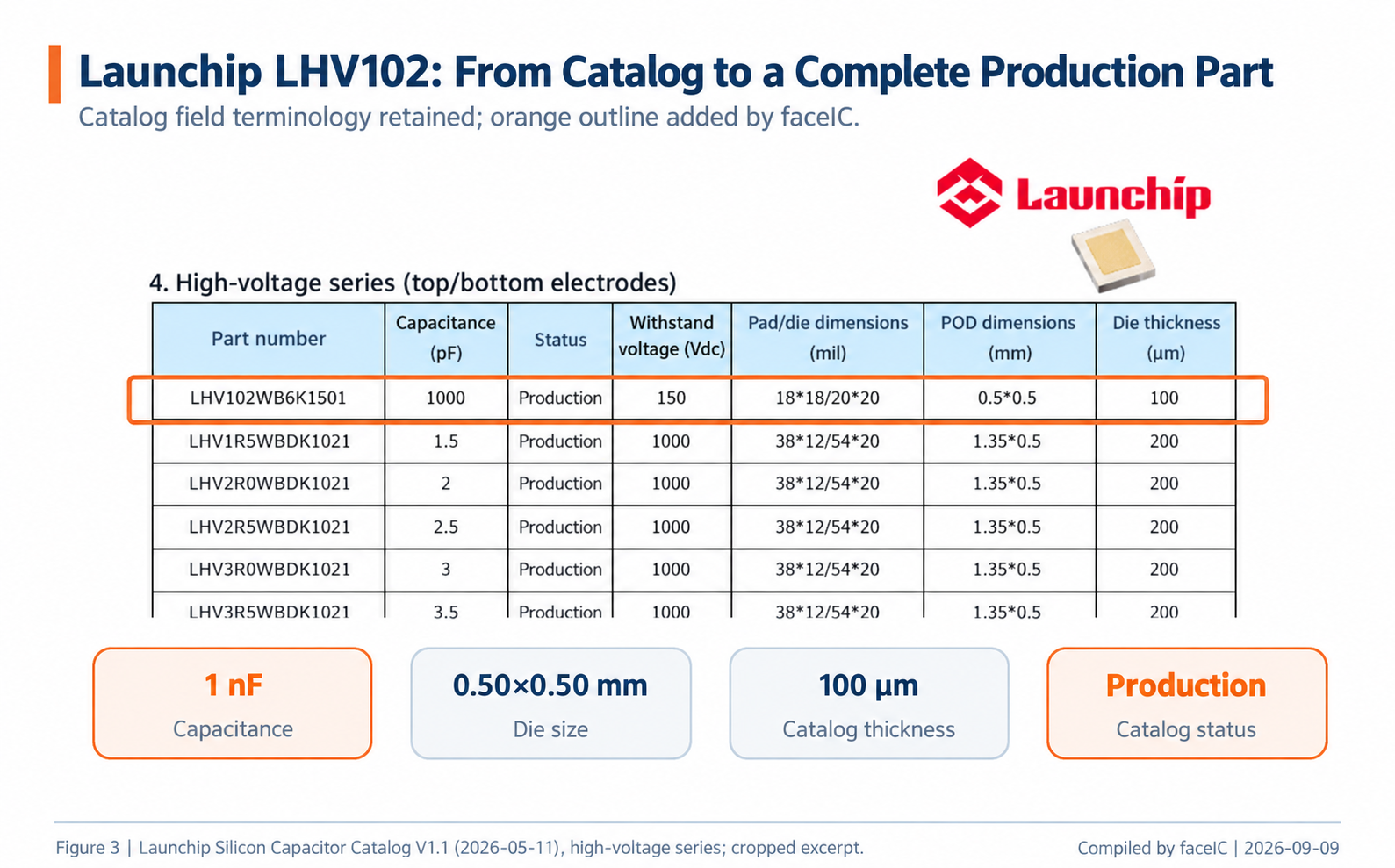
Launchip's May 2026 product catalog lists this part as in mass production, with a 0.50 × 0.50 mm die and a thickness of 100 μm. It provides delivery codes for blue tape and wafers, and indicates that thickness can be customized.
From an industry perspective, its value is not simply a claim of smaller size or lower ESL. It brings together a low profile, top and bottom electrodes, defined voltage limits and a production part number. That makes it a concrete domestic silicon-capacitor option for dimensional matching, assembly design and sample validation.
4. Meeting the datasheet limits is only the start of LiDAR validation
Passing a static specification review only qualifies a candidate for further evaluation. In the actual transmitter circuit, engineers still need to verify peak pulse current, pulse width, repetition frequency and maximum dV/dt, as well as installed voltage and current waveforms, overshoot and ringing.
For long-term repetitive operation, temperature rise, capacitance drift, leakage changes and pulse-cycle life also require evaluation. Silicon capacitors cannot be assumed to outperform MLCCs in every case, nor can system lifetime be inferred from a single impedance curve.
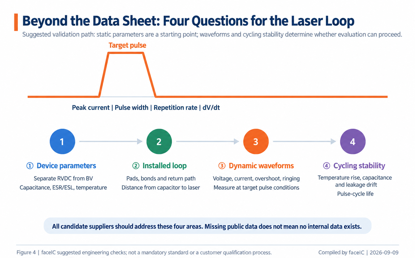
These questions apply to every candidate, not only Launchip. A data point missing from public documentation does not mean the manufacturer has not tested it internally. During qualification, supplier and customer need to confirm performance at the intended voltage, pulse width, repetition frequency and assembly configuration.
For engineering and procurement teams, a sound sequence is to narrow the field by mounting location and working voltage, compare the parasitics and temperature limits of complete part numbers, and then test samples in the actual circuit. Choosing a preferred material first and looking for supporting evidence afterward reverses that process.
Conclusion: the connection to the pulse loop matters
Fenghua represents the mature board-level MLCC route. FOIN Micro offers domestic top-and-bottom-electrode products with lower capacitance and high breakdown voltage. Murata has a broader vertical silicon-capacitor range, while MACOM addresses high-working-voltage bare-die requirements. These suppliers are not all competing under the same constraints.
Launchip's opportunity is not to replace every high-voltage MLCC. It is to offer a domestic silicon-capacitor option with clearly defined limits where space is restricted and connection paths are particularly sensitive.
Whether LHV102 qualifies for a project depends on consistently achieving the target pulse performance in the installed configuration, not on the labels “1 nF” and “150 V” alone. The datasheet starts the evaluation; circuit design and project validation determine the practical value.
Source note: Compiled by ic.net from public manufacturer documentation, the TI reference design and the LHV102 specifications supplied by Launchip. Please credit “Launchip Technology” when citing Launchip data and “Compiled by ic.net” when citing the analytical figures. This article is for industry discussion. Confirm specifications, availability and suitability with the manufacturer and through project validation.