
“Will silicon capacitors replace MLCCs?” sounds like a direct question, but it can send component selection in the wrong direction.
When engineers build a BOM, they do not start with silicon versus ceramic. They first ask where the capacitor will sit: on the PCB, close to the load, or in the package substrate. Is the rail 1.35 V or higher? How much effective capacitance is required across the target frequency range? How much Z-height remains? Once those questions are answered, much of the material choice has already been made.
This article therefore does not rank silicon capacitors against MLCCs as product families. It follows three 1 μF parts designed for different jobs: Yuyang Technology C0201X5R105M6R3NCZ, TDK C0510X5R0J105M030BC, and Launchip LHC105SA4K0032.
1. Start with BOM position: the same 1 μF label does not mean the same job
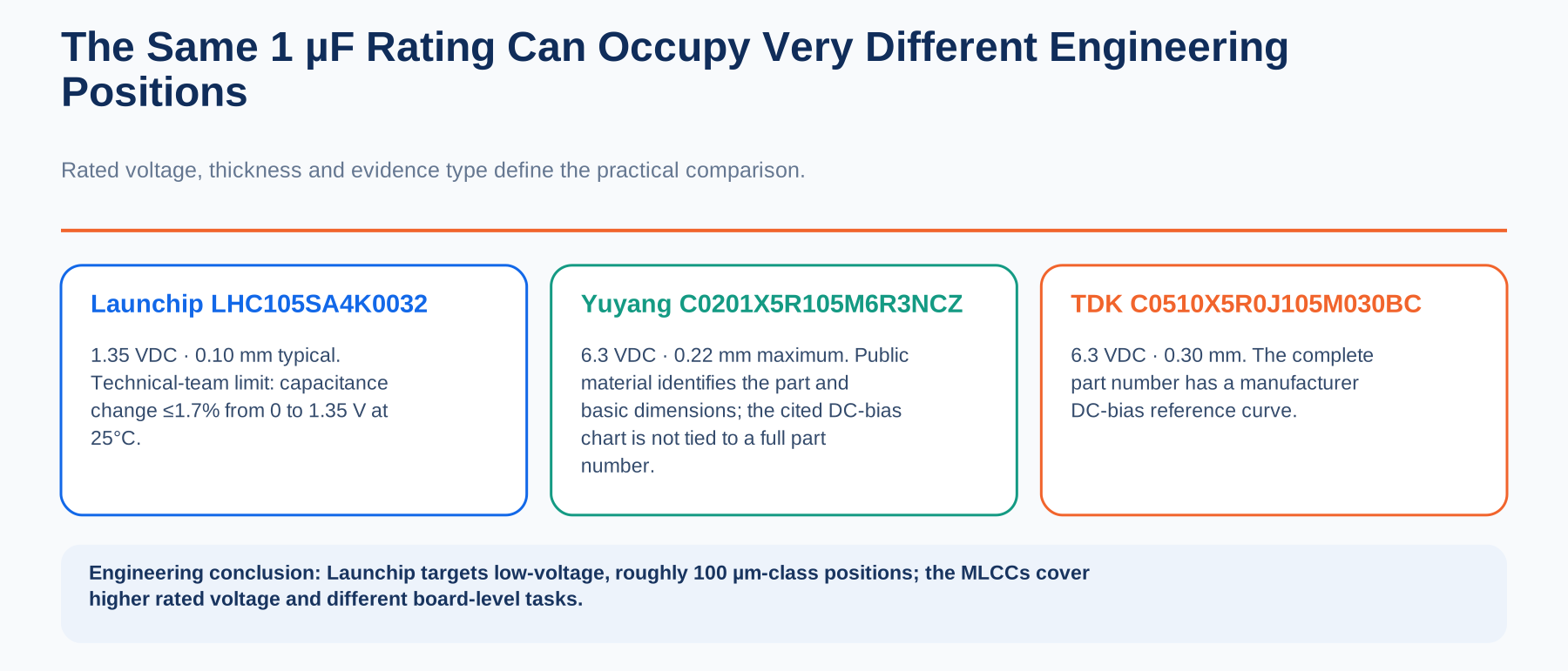
Yuyang Technology C0201X5R105M6R3NCZ is a 1 μF, 6.3 VDC, 0201 X5R MLCC with a published maximum thickness of 0.22 mm. It represents the board-level direction taken by China-made MLCCs: compress package size, capacitance and thickness while retaining a relatively high voltage rating and an established surface-mount supply chain.
TDK C0510X5R0J105M030BC is also rated at 1 μF and 6.3 VDC, but uses a 0204 reverse-geometry package and is 0.30 mm thick. Its purpose is not simply to shrink the footprint. Reorienting the terminals shortens the local board-level current loop, making the part suitable for low-parasitic decoupling close to a load.
Launchip LHC105SA4K0032 places 1 μF on a 1.35 VDC rail in a 0204 outline with a typical thickness of 0.10 mm. It is aimed at near-die locations and assemblies with tight height limits. Thickness can also be adjusted for the application, with 75 μm and 200 μm options cited for different package and assembly requirements. Instead of competing with the broad voltage and application range of MLCCs, it targets a narrower problem: low-voltage rails, thin spaces and a capacitance boundary that must be budgeted more explicitly.
All three parts carry a 1 μF label, but they are not drop-in substitutes. Yuyang focuses on board-level miniaturisation, TDK on reverse geometry and low local parasitics, and Launchip on low-voltage near-die decoupling in roughly 100 μm of height. The first selection question is not which headline specification looks best, but whether the parts are solving the same problem.
2. DC bias and effective capacitance: compare the evidence before the materials
Nominal capacitance, Cnom, is an initial value measured under specified temperature, frequency and AC test conditions. In a real circuit, tolerance, DC bias, temperature, frequency, AC amplitude and long-term ageing all affect the effective capacitance, Ceff.
MLCCs should not be treated as one uniform group. C0G/NP0 dielectrics generally provide stable capacitance but have limited coverage at high capacitance in very small packages. DC bias is a particular concern for Class II ceramic dielectrics such as X5R and X7R. The amount of capacitance loss cannot be inferred from the three-character dielectric code alone; it must be evaluated using the complete part number and the manufacturer's curves.
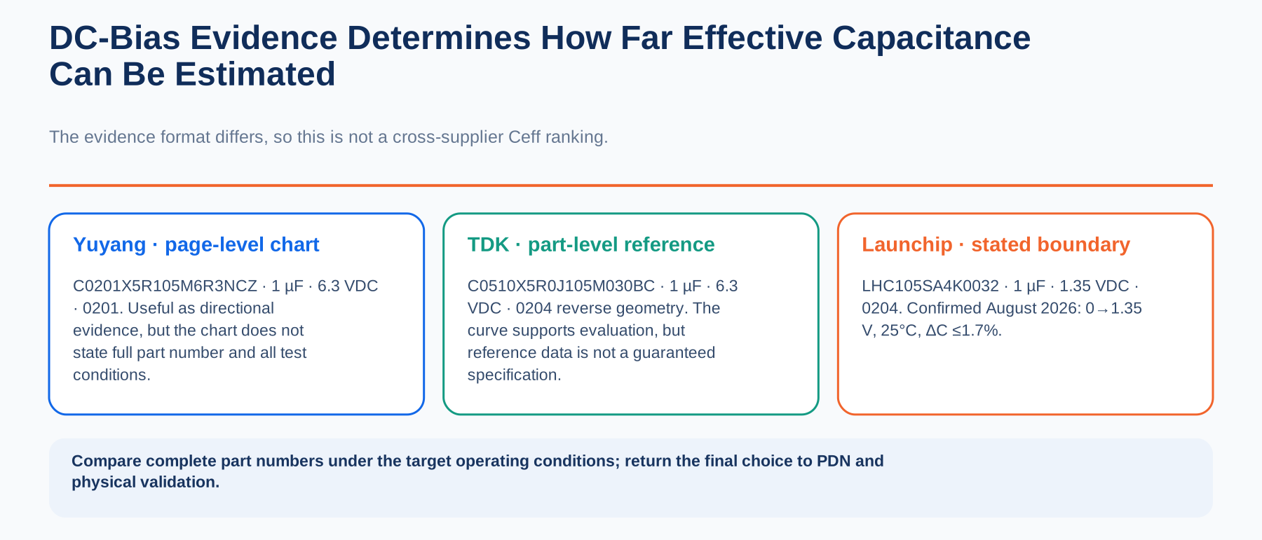
For Yuyang C0201X5R105M6R3NCZ, public material includes a DC-bias comparison between thin and conventional products. This shows that the thin X5R line is not presented without bias-characterisation data. The chart, however, does not identify a complete part number, and it does not disclose test temperature, frequency, AC level or whether the curve is a guaranteed specification.
TDK publishes a DC-bias reference curve for the complete C0510X5R0J105M030BC part number. Engineers can use it to estimate performance at the intended voltage, but reference data is not the same as a guaranteed limit.
Launchip uses a different form of disclosure. According to information confirmed by its technical team in August 2026, the capacitance change of LHC105SA4K0032 is no more than 1.7% as DC voltage rises from 0 V to the rated 1.35 V at 25°C. That gives engineers a stated upper bound that can be included in an early capacitance budget.
The useful comparison is therefore not “silicon is always more stable than X5R.” The real question is whether the supplier gives a sufficiently clear capacitance boundary for the complete part number at the target voltage. MLCCs remain efficient and mature for board-level decoupling with comfortable margin. In a low-voltage near-die PDN with tighter margin, the ability to calculate that boundary earlier carries more weight.
3. What differentiates Launchip LHC105: thickness and operating conditions tied to one part number
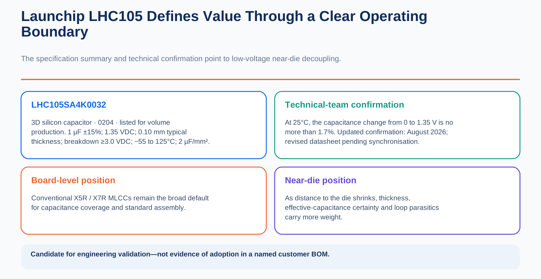
Launchip LHC105SA4K0032 has a nominal capacitance of 1 μF, a tolerance of ±15%, a rated operating voltage of 1.35 VDC, a breakdown voltage of at least 3.0 VDC, and an operating-temperature range of −55°C to 125°C. Read separately, those values still look like an ordinary specification table.
The differentiation comes from their combination. The 1.35 V rating maps to a low-voltage rail; 1 μF provides local decoupling; the typical 0.10 mm thickness addresses Z-height constraints; and the stated maximum 1.7% change from 0 to 1.35 V at 25°C defines a specific operating boundary.
In other words, Launchip's advantage is not one isolated extreme. It ties target voltage, an effective-capacitance boundary and customisable thickness to a complete part number.
Its 0.54 × 1.04 × 0.10 mm dimensions and published capacitance density of 2 μF/mm² also make it a candidate for locations beneath a BGA, in a package substrate or close to a die. Candidate is the important word: the public data supports engineering evaluation, but does not prove placement in the production BOM of a named AI-chip customer.
Launchip does not need to match the breadth of an MLCC catalogue. Its more realistic opportunity is to become a defined alternative where the rail is low-voltage, the capacitor is close to the die, height is constrained and the capacitance margin must be calculated more tightly.
4. MLCCs remain the default; silicon capacitors enter a few critical positions
For board-level capacitors that need higher rated voltage, many capacitance options, mature placement processes and high-volume supply, conventional X5R and X7R MLCCs retain clear advantages. Where the local loop near a load must be shortened, reverse-geometry, three-terminal and low-ESL MLCCs remain important options.
Near a die on a low-voltage rail with large transient current and tight height limits, effective-capacitance certainty, component thickness and mounting-loop parasitics become more important. That is where a silicon capacitor is more likely to enter the candidate set. It does not need to replace the complete MLCC BOM. Solving a small number of critical positions that conventional parts cannot satisfy simultaneously is enough to create value.
The correct selection order is therefore: define the BOM position and working voltage, calculate effective capacitance, compare thickness, mounting method and parasitics, and finally validate the choice through PDN and board-level testing. A shared 1 μF label is not a reason to compare price or static specifications directly.
Conclusion: the question is which device owns this section of the PDN
The three 1 μF parts represent three distinct selection paths. Conventional X5R/X7R MLCCs remain the main choice for board-level capacitance, higher rated voltage, mature assembly and broad supply. Reverse-geometry and low-ESL MLCCs are better suited to shortening the board-level loop near the load. When the rail moves into the 1.35 V range, Z-height approaches 100 μm and the effective-capacitance boundary must be known in advance, Launchip LHC105 becomes a more specific candidate.
That is the practical division of labour between silicon capacitors and MLCCs: MLCCs continue to cover most of the BOM, while silicon capacitors enter fewer but more critical positions. The notable point about Launchip's 1 μF device is not simply that a China-made silicon capacitor exists. It is that low voltage, ultra-thin construction and a calculable capacitance boundary have been combined in a part that is ready for engineering validation.
Original-source note: Product data was compiled by Launchip Technology in August 2026. Please credit “Launchip Technology” when citing this article. Sources include the Launchip Silicon Capacitor Device Datasheet V1.1 dated May 11, 2026, and information confirmed by the Launchip technical team in August 2026.